

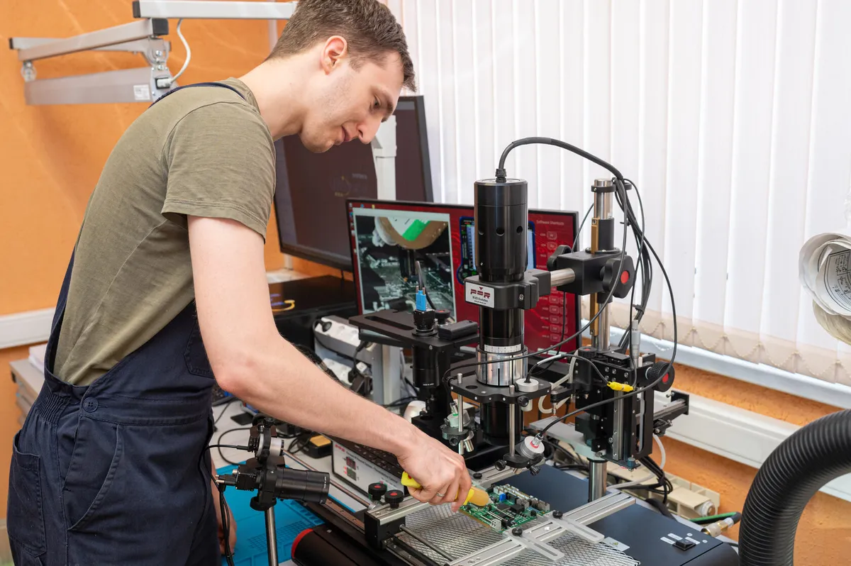
A good circuit board repair does not end with soldering. After components are replaced, some hidden defects only appear under working load, and it is post-repair acceptance testing that separates a reliably restored unit from one that will fail a week later in the field. Burn-in, running the board under load, is the key stage of this check.
Why soldering alone is not enough
Right after repair a board can look healthy: it powers on, passes a basic check, shows correct voltages. But a static test does not catch everything. A cold solder joint, a microcrack in a plated-through hole, a component sitting at the edge of its parametric tolerance - all of these pass a short check calmly and only reveal themselves once the assembly heats up and runs under current for several hours.
That is exactly why we do not hand a board back straight after repair. First it has to prove that it holds load under the same conditions in which it will run on real equipment.
What defects load draws out
The hidden defects a static check misses are fairly typical. A cold solder joint holds contact while the joint is cold, but as it heats the resistance climbs and the circuit starts to drop out. A microcrack in a plated-through hole behaves the same way: thermal expansion alternately closes and opens the contact. A component whose parameters sit at the edge of tolerance runs fine at room temperature, yet under load drifts out of spec and drags neighboring nodes with it.
A separate category is degradation under current. Electrolytic capacitors with dried-out electrolyte, power transistors with degraded heat dissipation, drivers at the limit of their dissipated power reveal themselves only when working current flows through them for several hours. A quick multimeter check passes such nodes; burn-in does not.
What burn-in is and infant mortality
The term burn-in describes prolonged operation of a device under load in order to expose early failures. Electronics has a characteristic reliability curve: in the first hours and days the failure rate is elevated (so-called infant mortality), followed by a long period of stable operation, and only near the end of service life do failures rise again due to wear.
The purpose of burn-in is to pass through the dangerous early part of that curve in the workshop rather than at the customer’s site. If a board has a weak spot introduced by a defective component or a strained solder joint, load and heat will draw it out here, on the bench, where a failure costs nothing.
What acceptance testing includes
Our post-repair acceptance testing consists of several stages:
- Multiple power-on and power-off cycles - they check behavior at power-up, when inrush currents pass through the board.
- A load profile based on customer requirements - the board runs under conditions close to real operation rather than idling.
- Thermal cycling - alternating heating and cooling stresses solder joints and plated-through holes through the different thermal expansion of materials and reveals fatigue defects.
- Parameter logging before and after - voltages, currents and node temperatures are recorded so the state of the board can be compared objectively at input and output.
Thermal cycling matters especially: most solder failures are tied not to a single heating event but to repeated cycles of expansion and contraction. Running several cycles on the bench models months of operation in real conditions.
Standards and ESD protection
Testing relies on industry standards. Solder quality is assessed against IPC-A-610 criteria, while conductor and plated-through-hole repair follows IPC-7711/7721. This is not a formality: a single standard delivers a reproducible, verifiable result instead of a judgment by eye.
All work with the board follows ESD controls, protection against electrostatic discharge. A discharge of a few hundred volts, imperceptible to a person, can damage a sensitive component invisibly, and such a defect is also hidden: it will surface later, already under load. Grounded workstations, wrist straps and antistatic packaging are a mandatory part of the process.
For boards that operate in humid, dusty or chemically aggressive environments, a conformal coating is applied after a successful burn-in. It protects the assemblies from moisture and contamination and extends the mean time between failures in real service.
What the customer gains
The point of all this is predictability. A board that has passed burn-in and thermal cycling, with logged parameters, is not a promise but a measured result. We know it ran under load, survived thermal cycles and did not fail on the most dangerous part of the reliability curve.
Each test leaves a record: which regimes the board went through, which parameters were logged before and after, and how long it ran. For critical equipment this is not bureaucracy but traceability: if a question about the unit arises a year later, there is an objective baseline rather than verbal assurances. That approach saves everyone time and settles any dispute about the condition in which the board left the workshop.
That is why we back our repairs with a warranty. Acceptance testing is what turns a restored unit into a reliable one, not merely one that works at the moment of handover. We explain why component-level repair is generally more cost-effective than a module swap in a separate article, and the logic of repairing instead of buying new on our company philosophy page.
This check is a standard step before equipment leaves our workshop. If you need industrial electronics repaired with full acceptance testing rather than just a component swap, get in touch: we will discuss the load profile for your equipment and the scope of testing.