

Metro traction inverters operate under constant start-stop cycles. At every station the train accelerates and brakes, and all that energy flows through the inverter’s power switches. Power-stage overheating and thermal paste degradation are the most common failure drivers we see during repair.
The metro does not forgive downtime: headways are tight, depots are overloaded, and new units take a long time to source and cost a lot. That is why component-level inverter repair is often the only sensible option. Below we break down which power-stage defects show up most often and how we bring a unit back into service.
Why power switches fail
The core working element of an inverter is the IGBT module. It switches large currents at high frequency, and every switching event releases heat. If heat removal degrades, the die overheats and deteriorates.
The first enemy is the thermal interface. The thermal paste between the module and the heatsink dries out over time, thermal resistance rises, and the module runs hotter at the same load. It is a classic chain: dry paste, overheating, thermal breakdown of the die.
The second factor is thermal cycling. Constant starts and stops mean constant heating and cooling cycles. Different coefficients of thermal expansion inside the module cause fatigue in soldered and bonded joints, delamination of the die from the substrate, and lift-off of the bond wires.
The third is the gate drivers. If a driver produces a non-optimal turn-on edge, the IGBT stays in its active region longer and heats up more. A driver failure often takes the power module down with it.
What we inspect first
We start diagnostics without applying full power, so as not to make a possible defect worse. The order is as follows:
- The state of the IGBT modules and gate drivers: we check the junctions, gate resistance, and control characteristics.
- The control-circuit power rails and the driver reference voltages.
- Heatsink cooling: flatness of contact, condition of the thermal paste, and absence of air gaps.
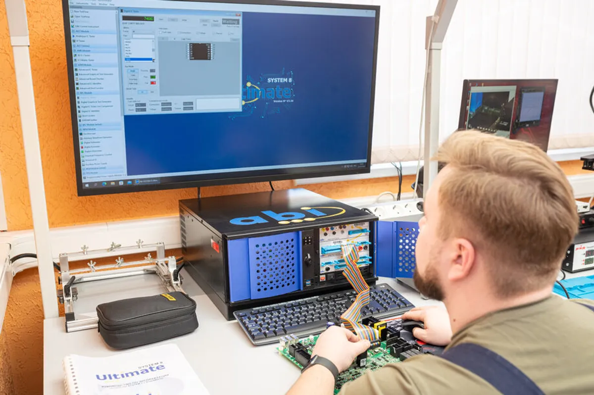
Next we connect the ABI BoardMaster and compare the control board’s nets against a reference to localize deviations. We described the method in detail in our article on fault localization with BoardMaster.
Thermal scanning
Before soldering anything, we capture the thermal image of the unit under load. The thermal camera reveals local hot spots that point to rising contact resistance, a degraded thermal interface, or an incipient breakdown.
This saves the customer time and money: we do not swap components blindly, we go straight to the problem area. There is more on the method in our piece on thermal scanning before repair.
Power-stage replacement and solder inspection
Defective IGBT modules and drivers are replaced with proven, parametrically matched equivalents. Landing pads are restored to the IPC-A-610 standard, and all work is done under ESD control and follows the IPC-7711/7721 rework standard.
After replacing a power module, we always check the gate-control circuits: the gate resistors, the driver’s optical isolation, and the shoot-through protection. A damaged driver left unattended will destroy the new IGBT within the first hours of operation, so we do not stop at replacing the obviously burned part.
The inverter control boards often carry ICs in BGA packages. When the solder balls have degraded, we reball the device and verify the restored joints by X-ray against the IPC-A-610 criteria: we assess ball fill, the absence of voids, and the absence of bridging between leads.
When mounting the power module, we apply fresh thermal interface material with controlled layer thickness and tightening torque. This returns thermal resistance to its rated value and extends the life of the switch. Where needed, we also refresh the snubber circuits and the DC-link filter capacitors: their degradation raises the load on the power switches too and speeds up their wear.
Bench testing under load
After the power stage is replaced, the unit runs through bench testing under a load that imitates real acceleration and braking cycles. We monitor module temperature, the shape of the switched currents, and the behavior of the protection circuits.
Burn-in testing weeds out hidden defects that a static check would miss. We explained why a mandatory burn-in matters in our article on post-repair burn-in testing.
Why an inverter failure on the line is dangerous
The inverter is the heart of the traction drive. Its failure means the car loses tractive effort and cannot keep moving under load. On the metro’s tight schedule this is a disruption to the whole line, not just one train, so the cost of downtime here is especially high.
For this reason we approach inverter units with a reliability margin. We do not just clear the current defect, we also check the neighboring circuits that are running at their limit. An overheated node often manages to damage a gate driver or a supply rail, and if that goes unnoticed, the unit comes back with a repeat failure before long.
Repair instead of replacing an expensive unit
A new inverter unit for the metro is expensive, and lead times can run into months. Yet the defect is usually local: one punctured IGBT module, dried-out thermal paste, or a failed driver. Replacing the whole unit over that makes no sense.
Component-level repair restores the inverter to its original characteristics for less money and many times faster. We rebuild the damaged node specifically and verify the rest of the circuit on the bench.
Service life after repair
A properly executed power-stage repair matches the service life of a factory unit. The key conditions are parametrically matched IGBT modules, fresh thermal interface material with controlled layer thickness and tightening torque, and a mandatory burn-in under load before release.
At intake we record the initial state of the unit, and we return it with a description of the work done and operating recommendations. A transparent report before and after the repair is our basic principle for working with a customer’s fleet.
We also recommend a preventive routine: checking the condition of the thermal interface and the tightening of the power modules within the maintenance cycle. Thermal paste dries out gradually, and a scheduled replacement costs less than an emergency repair after a thermal breakdown of an IGBT.
The bottom line
Metro traction inverters fail predictably: overheating, dry thermal paste, joint fatigue inside the IGBT modules. All of these defects respond to component-level repair if you approach the job methodically: diagnostics, thermal imaging, targeted replacement, and burn-in under load.
We restore these units as part of our metro electronics repair service and apply the same approach to rail equipment. Our customers include metro operators. If an inverter unit in your fleet needs repair, request a diagnostics quote and get a transparent report before any work begins.