

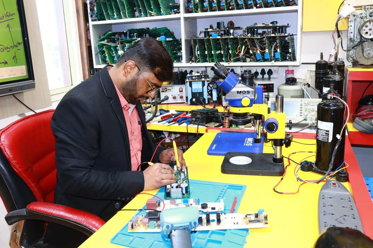
Board diagnostics without schematics on the ABI BoardMaster series 8000 is what lets us repair industrial electronics that no longer have any documentation or manufacturer support. We do not guess which module to swap. Instead we measure the electrical behavior of every pin and locate the point of failure by its deviation from the norm. Below we explain in detail what we actually do at this bench, how VI testing works, and why the known-good comparison method speeds up repair of equipment that is out of production.
What the ABI BoardMaster series 8000 is
The ABI BoardMaster is a modular system for functional and analog testing of printed circuit boards, built by ABI Electronics. The series 8000 combines several instruments in one bench: signal generators, an oscilloscope, programmable power supplies, an IC tester and, most important for us, a VI testing module based on analog signature analysis.
The core value of the instrument is that it works with a method that needs no schematic. For industrial boards that are 15 to 20 years old there is usually no documentation left: the maker has gone, the schematics are closed or lost. BoardMaster lets us diagnose such a board by the actual behavior of its circuits rather than by paperwork that does not exist.
We use the bench as our primary incoming diagnostic tool. A board reaches it before an engineer ever picks up a soldering iron, and this is where the report on what has failed is built.
VI testing: the voltage-current signature
VI testing (Voltage-Current) is the foundation of how BoardMaster works. An alternating signal with limited current is applied to a component pin, and the instrument plots current against voltage. The result is a characteristic curve, an analog signature, that is unique to each type of component.
A healthy resistor produces a sloped straight line whose angle depends on its resistance. A capacitor draws an ellipse. A healthy diode or transistor junction gives a characteristic knee. An inductor behaves differently at different frequencies. An experienced engineer reads these curves like a language: the shape of the signature reveals what component is connected to the pin and what condition it is in.
The key feature of the method is that testing runs with no operating power applied to the board. We can safely check nodes that on a normal power-up would short out and drag adjacent circuits down with them. For power industrial electronics, where one blown switch can damage half the circuit, this matters enormously.
Ranges: voltage, current, frequency
The same point on a board looks different depending on the test regime, so BoardMaster captures the signature across several ranges.
- Voltage. A low test voltage gently checks sensitive logic inputs and does not activate semiconductor junctions. A higher voltage better reveals breakdowns and leakage in power circuits.
- Current. The current limit sets how deeply we load the circuit. A small current is safe for thin traces and low-power nodes, while a larger current exposes the behavior of high-power components.
- Frequency. Changing the signal frequency helps tell a capacitor from an inductor and reveals reactive elements that are invisible at a single frequency.
The engineer chooses the combination of ranges to match the type of circuit. We assess the same pin from several angles so as not to miss a defect that shows up only in one regime. It is this multi-range approach that separates sound diagnostics from a shallow check.
The comparison method: reference board versus sample
A signature on its own says little until there is something to compare it against. So the main working method on BoardMaster is known-good comparison. We capture VI characteristics from a board that is known to be good, then run the same points on the faulty sample. The instrument highlights the differences across circuits and shows at once where the signature has drifted from normal.
The nature of the deviation tells us the type of defect. A shifted capacitor ellipse points to leakage or loss of capacitance. A straight line instead of a knee on a junction means a shorted semiconductor. A break in the characteristic means an open circuit or a cold solder joint. This approach sharply narrows the search: instead of the whole board, the engineer works with a few suspect points.
When there is no reference board, we use two workarounds. The first is signature libraries built up for common components. The second, most convenient for industrial modules, is comparing identical channels within a single board. Many modules contain repeating sections: several identical input-output channels, parallel power legs. A working channel becomes a live reference for the failed one, and again no schematic is needed.
Working with ICs and digital nodes
An analog signature is captured from IC pins too, but for digital components BoardMaster offers more. The series 8000 bench holds a test library for tens of thousands of digital ICs and can check them functionally: apply test vectors to the inputs and compare the output response with the reference logic.
This lets us tell healthy logic from degraded, find a stuck output or an internal open inside the package that is impossible to spot by eye. For non-standard and custom ICs that are not in the library, we fall back to known-good comparison across the pins and judge behavior by the signature.
This dual approach, analog and functional, covers most failures on the digital part of a board without a single reference to a schematic.
Why this speeds up repair of out-of-production equipment
The main pain for an industrial customer is equipment that is officially no longer supplied. The board cannot be bought, the supplier offers only a whole-block replacement at the price of a new unit, or simply shrugs. Diagnostics without a schematic change that situation.
BoardMaster lets us localize a failure in one pass on a board for which we have no documentation at all. We do not spend weeks reverse-engineering a schematic. We measure circuit behavior directly and find the defective component. This moves the repair from the category of open-ended work into a predictable task with clear timing and cost.
Another gain is repeatability. Diagnostics are built on measurable signatures rather than on the intuition of one technician. Another engineer, repeating the same points on the same board, gets the same deviations. For the customer this means the quality of diagnostics does not depend on who is at the bench today. We covered the logic of localization in more depth in our piece on fault localization with BoardMaster.
Where VI testing is complemented by other methods
BoardMaster shows the electrical behavior of circuits, but it cannot see what is hidden under a package or what appears only under load. So on complex boards we combine methods.
A thermal camera catches components that heat up beyond normal under operating power. A leakage that the signature shows as a slight deviation looks like a clear hotspot on a heat map. We cover this in a separate article on thermal imaging in electronics diagnostics and on the thermal scan before repair.
X-ray inspection is needed where pins are physically out of reach of a probe: under BGA components the solder is invisible to the eye, and joint quality can only be judged by X-ray, as we describe in our article on BGA solder joint inspection. The combination of three methods gives a full picture: electrical, thermal and physical.
ESD and repair standards
Accurate diagnostics are pointless if we introduce new defects in the process. Industrial electronics are sensitive to electrostatic discharge, so all work at the bench follows ESD requirements: grounded wrist straps, antistatic mats, conductive containers for boards.
The subsequent repair is carried out to the IPC-7711 and IPC-7721 standards, and quality acceptance is checked against IPC-A-610. This guarantees that after restoration a board meets the same requirements as it did in manufacturing. A strict process is part of our philosophy of repair rather than waste and of all the work in our workshop.
What this gives the customer
For the customer, diagnostics on the ABI BoardMaster turn into concrete benefits. A transparent report before any work begins shows exactly what has failed, so agreeing timing and cost happens without surprises. Component-level repair instead of replacing a whole module noticeably lowers cost, especially for obsolete boards that can no longer be bought. We apply this approach in projects for rail transport, the metro and marine electronics.
If you have a board the supplier offers only to replace whole, bring it in for diagnostics. We will capture the signatures, localize the failure without a schematic, and tell you honestly what can be restored and what cannot. You can learn more about our workshop equipment and discuss your case through our contact page.