

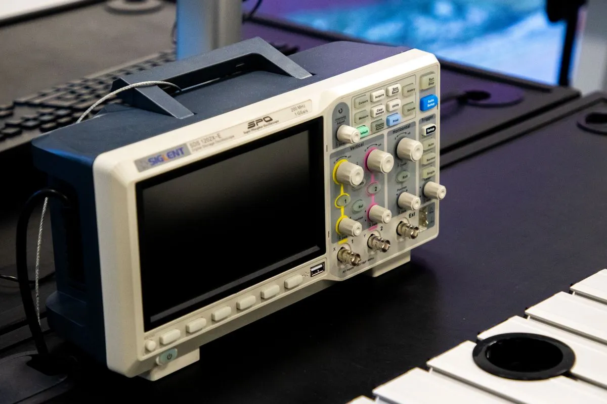
A digital oscilloscope in board repair is the instrument that shows an electrical signal over time and turns guesses about a fault into precise observation. A multimeter tells you a voltage is present, but not what shape it actually has. An oscilloscope shows the shape, amplitude, frequency, edges and any dropouts in the signal. On industrial electronics these are exactly the details that most often separate a healthy node from one that is about to let you down. Below we explain what we look at with the oscilloscope on different nodes of a board and how it helps find the real cause of a failure.
Checking clocking and reference frequencies
The first thing we check on a board with a processor or controller is clocking. Without a clean clock signal no digital node will start. We put the probe on the pins of the crystal resonator or oscillator and look at whether there is oscillation at all, what its amplitude is and whether the waveform is stable.
Typical defects are visible immediately. A stalled oscillator produces a flat line instead of a sine wave or square wave. A reduced amplitude points to a degraded crystal or leakage across the load capacitors. Jitter on the edges signals unstable oscillator power or interference. On boards that work through vibration and temperature swings, the crystal and its surrounding parts are often the weak link, and the oscilloscope catches this in seconds.
SPI, I2C and UART buses
Digital buses are the language the chips on a board use to talk to each other. If bus traffic is broken, a node behaves as if dead even though power and clocking are fine. An oscilloscope with protocol decoding shows not only the waveform but the actual transmitted bytes.
On an I2C bus we look at the SDA and SCL lines: is there a pull-up to the supply, do the edges reach the required logic level, does the slave device respond with an acknowledge. An SDA line stuck low is a classic sign that one of the chips on the bus has failed and is holding the bus down. On SPI we watch the clock line, data and chip select, checking that data changes in the correct phase relative to the clock. On UART the oscilloscope helps confirm the baud rate and see that the transmitter is actually sending frames rather than staying silent.
This check immediately separates the healthy part of the circuit from the faulty one. If the master sends a request and the slave does not answer, the search area narrows to a specific chip and its power supply.
Power and ripple
The oscilloscope is indispensable for checking power. A multimeter shows five volts on the rail, but it will not show that on top of those five volts sits a few hundred millivolts of ripple that upsets the logic. We switch the probe to AC coupling, reference the power line and look at the ripple level.
On switching converters we monitor the peak-to-peak ripple and its frequency. Elevated ripple almost always points to degraded electrolytic capacitors: their equivalent series resistance rises and the filter can no longer hold. The rail also shows switching spikes at the moment the power switch commutates, and sag under load. We check each secondary rail separately, because a sag on just one of them is often the root of the problem rather than a general converter failure. The oscilloscope pairs well with the bench power supply, which we use to feed the board a controlled voltage and current during these measurements.
Logic levels and edges
A digital circuit works correctly only as long as signals confidently reach the logic zero and logic one thresholds. Intermediate, blurred levels are a source of floating faults. The oscilloscope shows the real amplitude and edge steepness at logic inputs and outputs.
We look at whether the high level reaches the required voltage, whether the edge is slumped by parasitic capacitance or a sagging output, and whether there is ringing on the edges from poor line matching. An edge that is too shallow means the receiver may read the same signal now as a zero, now as a one, and the node runs unstably. Such defects are invisible to a multimeter and to visual inspection, and are found only on the oscilloscope screen.
Hunting signal dropouts and intermittent faults
The hardest faults are the intermittent ones: the board works, then it does not. This is where the strengths of a digital oscilloscope fully show. Unlike an analog one, it stores the event in memory and lets you catch a rare glitch.
We use single-shot capture and set the instrument to wait precisely for the anomaly. Glitch capture catches a spike lasting microseconds that resets the controller. Persistence mode shows the accumulated picture of the signal over a long time, and any rare dropout appears as a separate trace against the normal mass of signals. This is how we find clock dropouts on warm-up, brief power sags and interference that are impossible to see with an ordinary measurement.
Intermittent faults are often temperature related, so we combine oscilloscope monitoring with local heating or cooling of the suspect node and watch how the signal changes. This is the case where observing behavior in real time gives an answer no static measurement can.
Working with triggers and probes
The accuracy of oscilloscope diagnostics rests on two things: the right trigger and the right probe. The trigger sets the condition on which the instrument freezes the moment on screen. We set the capture not only on a level, but on an edge, on pulse width, on a protocol violation on the bus. A well chosen trigger turns a chaotic picture into a stable, readable event.
The probe matters just as much. For accurate measurements we use a compensated divider probe and always check its compensation before work, otherwise the edges will be distorted. We connect the probe ground as close as possible to the measurement point with a short lead: a long ground loop adds ringing and pickup that is easy to mistake for a board defect. On fast signals this rule is critical. All work follows electrostatic discharge protection requirements: grounded wrist straps, antistatic mats and conductive containers, so that the measurement procedure itself does not introduce a new defect into the board.
What we do with the oscilloscope
In our process the oscilloscope is not a separate stage but a working tool that accompanies diagnostics from the first power-up to the final check. With it we verify clocking and reference frequencies, read bus traffic, assess power ripple, monitor logic levels and edges, and catch intermittent faults. The oscilloscope complements our other methods: analog signature analysis on ABI BoardMaster finds the faulty component without applying power, while the oscilloscope shows how the node behaves under working voltage.
This approach is especially valuable on boards for rail transport and metro systems, where an intermittent fault can take equipment out of service at the worst possible moment, and a replacement for a discontinued board can no longer be bought. The full range of our diagnostic gear is described on the equipment page.
If you have a board with a floating fault you cannot pin down, bring it in. We will capture waveforms at every key node, find the moment of failure and tell you honestly what can be restored. You can discuss the task through our contact page.