

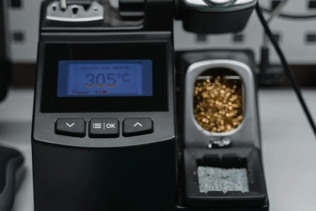
A hot air rework station is one of the core tools in our workshop for component-level repair of industrial electronics. It is the station on which we remove and install surface-mount parts: from tiny chip resistors and capacitors to multi-lead QFP and QFN packages. Below we go through in detail what we can do on this instrument, how we choose the thermal profile and how we protect the board from overheating.
How hot air soldering works
The principle of a hot air station is simple: a stream of hot air through a nozzle heats the component leads and the solder to reflow temperature without touching the board mechanically. This lets us take off and put on parts whose leads are hidden under the package or spaced too tightly for a regular iron.
The key parameters we control are air temperature, airflow and nozzle diameter. Too strong a flow blows away small neighbouring parts and scatters the flux, too weak a flow fails to heat the joint evenly. For each package type and board size we select the nozzle and the mode separately, rather than working on a single universal setting.
The hot air station complements the rest of the workshop equipment. Ball-grid packages call for a dedicated BGA station and reballing process, while hot air remains the primary tool for planar packages with leads around the perimeter.
Removing SMD components
Removal is the first and often the riskiest stage. An overheated or torn-off component can take the contact pads with it, and along with them part of the board’s conductive pattern. That is why we follow a proven sequence.
First the board and the joint area are heated evenly to avoid thermal shock. Then flux is applied to the leads, which improves heat transfer and protects the solder from oxidation. The component is lifted only once all the solder around the perimeter has gone into the liquid phase - pulling any earlier is not allowed.
The main removal techniques on the station:
- Small chip parts (resistors, capacitors) are lifted with local heat and careful tweezer work.
- Multi-lead QFP and QFN packages are heated evenly across the whole body so that all leads release at the same time.
- Connectors and shields with high thermal mass need the board preheated from below, otherwise the top flow is not enough.
After the component is removed the pads are cleaned of old solder with wick and refreshed with new solder, so the new placement lands on a prepared surface.
Placement and work with QFP and QFN
Installing a new component is the reverse task, but with its own subtleties. QFP packages have gull-wing leads around the perimeter, and the main problem here is solder bridges between adjacent legs. QFN and DFN packages have no leads as such - their pads are on the bottom of the body, and the joint quality cannot be checked directly by eye.
During placement we align the component precisely to its footprint, apply the right amount of flux and solder paste and run an even heat up to reflow. Flux here works not only as an activator but also as a self-alignment aid: on reflow the surface tension forces pull the body onto the pads.
To verify the result we use a soldering microscope, and for the hidden QFN pads we assess the fillet shape and, where needed, X-ray inspection. Bridges are removed with wick, a shortage of solder is topped up locally. The work follows the IPC-A-610 acceptance criteria, which define the allowable fillet shape, wetting and the absence of shorts.
Choosing the thermal profile
The thermal profile is what separates a quality joint from a ruined board. The profile describes how temperature changes over time: preheat, the reflow peak and controlled cooling.
We tune the profile to the specific solder and package. Lead-free alloys reflow at a higher temperature than tin-lead ones, and the margin to the component’s limit temperature is smaller. The main principles we stick to:
- A gentle preheat to activate the flux and relieve internal stress without thermal shock.
- Enough time above liquidus, but no longer than needed - overheating destroys the flux and oxidises the solder.
- Controlled cooling, because a sharp drop gives brittle joints and warps the board.
When working with multilayer boards and high thermal-mass components we always use bottom preheating so as not to drive the top nozzle to its limit temperature. This reduces the risk of board delamination and damage to neighbouring parts.
Flux, wick and cleaning
Consumables directly affect the outcome. We choose the flux to match the task: fine QFN work needs an active flux with good flow, large pads need a more viscous gel. After soldering, any active flux residue is removed without fail, otherwise over time it causes corrosion and leakage currents.
Wick (tinned copper braid) is the main tool for removing excess solder, clearing bridges and cleaning pads before placement. Working the braid properly requires its own flux and precise heat: overheated braid tears the pads, underheated braid fails to pick up the solder.
Final cleaning of the board is a mandatory stage. We wash the repair area free of flux residue, and where necessary use ultrasonic cleaning for hard-to-reach spots under the packages. All removal, soldering and restoration operations are carried out within the IPC-7711 and IPC-7721 standards, which describe the allowable methods of PCB repair and rework.
Protecting neighbouring parts and connectors
Hot air does not tell the difference between the part being repaired and the one next to it. That is why protecting the surroundings is a separate part of the job. Plastic connectors, crystals, electrolytic capacitors and labels do not tolerate soldering temperature and warp easily from side flow.
What we do to protect them:
- Shield neighbouring areas with heat-resistant tape (Kapton) and dedicated shields.
- Direct the flow strictly onto the repair zone, choosing a narrow nozzle where parts are placed tightly.
- Remove or cover temperature-sensitive elements if they fall into the heating zone.
- Observe ESD requirements at every stage, because a static discharge kills sensitive chips no less than overheating does.
Common overheating mistakes
Most of the ruined boards brought to us after someone else’s repair suffered precisely from overheating. Understanding these mistakes is half of a quality job.
The most frequent problems we see:
- Lifted contact pads and traces due to too high a temperature or too long a heat.
- Delamination of a multilayer board, where the layers separate from overheating without bottom preheat.
- Bulged and leaking electrolytic capacitors next to the soldering zone.
- Thermal shock from rapid heating of a cold board, which gives microcracks in parts and joints.
- Destroyed flux and oxidised joints from exceeding the time above the reflow point.
We avoid these mistakes through a controlled profile, bottom preheat and constant temperature control. After soldering the board goes through a load check, which we covered in detail in the article on post-repair burn-in. Before a difficult repair we often take a thermal scan of the board to understand the starting state and not miss a hidden defect.
What we do on the hot air station
A summary of what this instrument does in our workshop: we remove and install the whole range of planar components, from small chip elements to fine-pitch QFP and QFN, restore contact pads, clear bridges and tune the thermal profile to the specific solder and package. All of it with protection of neighbouring elements and to IPC standards.
The hot air station rarely works alone: it is part of the overall component repair process, which includes diagnostics, fault localization and a final check. The full list of workshop equipment is gathered on the Equipment page.
If you have a board that needs an SMD component replaced, repair after overheating or pad restoration, bring it in. We will assess the state of the board and tell you honestly what can be done. You can discuss the task through our contact page.