

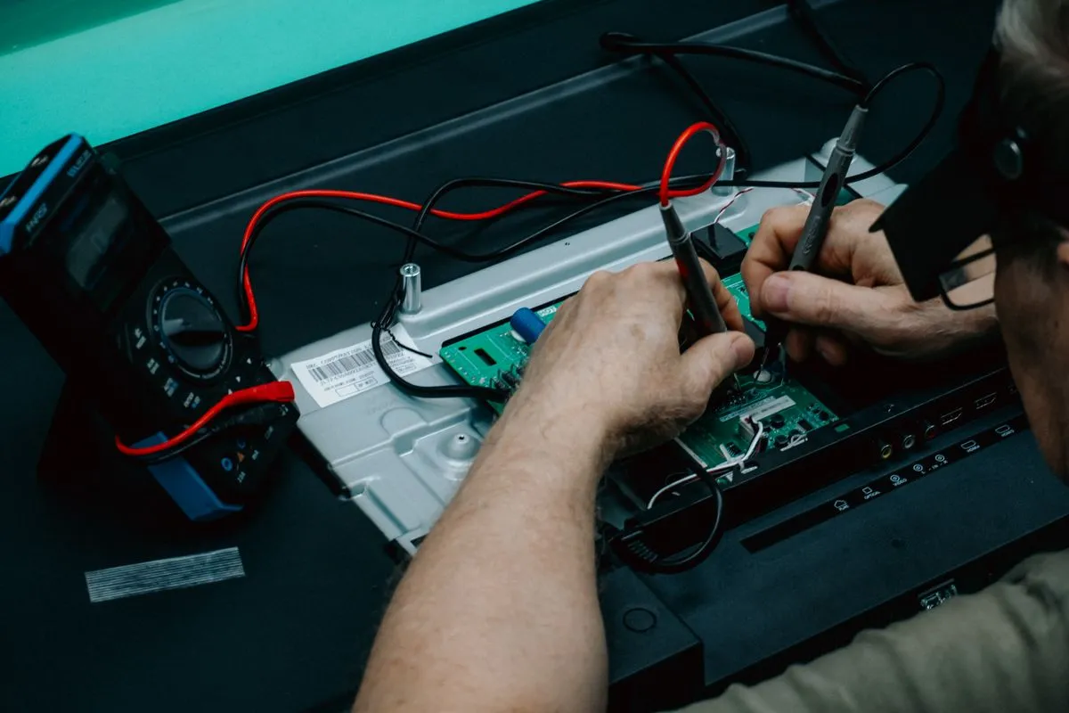
The LCR meter and bench multimeter are the basic measurement instruments without which component-level industrial electronics repair turns into guesswork. They give us precise numbers for every element on the board: resistance, capacitance, inductance, the equivalent series resistance of a capacitor, and the condition of diodes and transistors. We use them both when hunting for a fault and during incoming inspection of new components, so that after repair the board runs as reliably as it did in production. Below we explain what exactly we measure and why.
Two instruments for two jobs
The bench multimeter and the LCR meter complement each other. The multimeter is a universal meter for voltage, current and resistance with high accuracy and stability, plus semiconductor test functions. The bench form factor matters: a stationary instrument has higher resolution, steadier readings and easier two-hand operation, when one hand holds the board while the probes touch the contacts.
The LCR meter is a specialized instrument for measuring reactive components. The letters in its name are inductance L, capacitance C and resistance R. Unlike a simple multimeter, the LCR meter measures a component with an AC signal at a set frequency, so it sees not only the nominal value but also the quality of the element: losses, parasitic resistance and deviation from norm.
Together they cover almost the entire range of passive and semiconductor components found on industrial boards.
Resistance, capacitance and inductance
Let us start with the three basic quantities that form the foundation of any circuit.
Resistance we measure with both the multimeter and the LCR meter. On a board it is important not just to read a resistor value but to understand whether it has drifted from norm. Resistors degrade from overheating and ageing: their resistance rises, and in power circuits this changes the operating conditions of the whole schematic. A precise measurement lets us reject a drifted element before it causes a repeat failure.
Capacitance is critical for capacitors, of which there are dozens on a power board. We check whether the real capacitance matches the nominal. Electrolytic capacitors dry out over time, lose capacitance and stop smoothing the supply, which brings ripple and instability. The LCR meter shows the actual capacitance and immediately reveals sagging elements.
Inductance we measure on chokes, coils and transformers. An open or a shorted turn in a winding changes the inductance, and the LCR meter records it. For switching power supplies, of which there are many in industrial equipment, the condition of the chokes directly affects operability.
Capacitor ESR, the key diagnostic parameter
ESR measurement, the equivalent series resistance of a capacitor, deserves a separate mention. It is one of the most informative parameters in repair.
An ideal capacitor passes AC without loss, but a real one has a parasitic series resistance. In a healthy capacitor the ESR is low, while in a degraded one it rises even when the capacitance still looks normal. Elevated ESR is most often behind unstable power supply behaviour: the capacitor seems to hold its capacitance but can no longer handle the current ripple.
The LCR meter measures ESR at the working frequency, and this lets us find capacitors that are formally alive but effectively failed. A simple multimeter would show such a capacitor as good while the board keeps misbehaving. Measuring ESR turns this hidden problem into a concrete number and a clear decision to replace.
Testing diodes and transistors
Semiconductors are the second large group of components we control by measurement.
Diodes are tested in junction mode: the multimeter shows the forward voltage drop across the junction and the absence of conduction in reverse. A shorted diode conducts both ways, an open one does not conduct at all. From the voltage drop we also tell an ordinary silicon diode from a Schottky diode and from an LED.
Transistors, both bipolar and field-effect, we test by their junctions and by controllability. For a bipolar transistor these are two junctions that should behave like diodes, for a field-effect one it is the response to the control voltage on the gate. A junction breakdown or loss of controllability clearly points to a faulty switch. In the power circuits of industrial boards, shorted transistor switches are often the root cause of a failure and drag neighbouring circuits down with them.
We do these checks carefully, mindful of the power-off rule: suspicious semiconductors are safer to assess with measurements first and only then, if needed, apply voltage.
Incoming component control before installation
Measurements are needed not only when hunting a fault but also during incoming control. Before fitting a new component onto a customer board, we verify its parameters.
There are several reasons. Components can arrive faulty from the factory, especially from long-stored stock where electrolytic capacitors may have dried out before installation. Mislabelling happens too, when the marking does not match the real value. Finally, the industrial component market has counterfeits, and measurement is the first barrier that filters them out.
Incoming control includes checking the nominal value of resistors and capacitors, the capacitance and ESR of electrolytics, and the junction integrity of semiconductors. A component that fails the check does not reach the board. This guarantees that we do not swap one faulty element for another that was defective from the start and create a repeat failure.
Finding opens, shorts and rejecting parts
The multimeter is indispensable for finding opens and shorts on a board. In continuity mode it instantly shows the integrity of tracks and circuits, and measuring resistance across the power rails helps find a short before voltage is applied.
An element gone open breaks the circuit, and the instrument records it as zero or infinite conduction depending on the mode. A short in the power circuit is dangerous because, at power-up, it can damage half the schematic, so we always check the rails for shorts before the board first starts.
Rejection based on measurement results is the final filter. Every suspicious element gets a concrete number, and the decision to replace is made not on intuition but on a measured deviation from norm. This approach makes repair repeatable: another engineer, repeating the same measurements, arrives at the same conclusion.
How measurement fits into the repair process
The measurement instruments work in tandem with the rest of the workshop fleet. First we localize the faulty area, including by signature comparison in ABI BoardMaster diagnostics, and then confirm the diagnosis with targeted measurements of resistance, capacitance and ESR. Thermal imaging and X-ray add to the picture where leads are inaccessible to the probe, while the LCR meter and multimeter give a numerical assessment of every suspicious component.
All work follows ESD requirements: grounded wrist straps, antistatic mats and conductive packaging for boards and components. Soldering after rejection is done to IPC-7711 and IPC-7721 standards, and the assembly quality is judged against IPC-A-610. Precise measurements are pointless if a new defect is introduced in the process, so workbench discipline here is as important as the instrument itself.
This approach is part of our philosophy of repair, not waste and the foundation of component repair instead of module swap.
What the customer gets
For the customer, precise measurements mean a predictable result. We do not swap components at random, we find the specific element with a measured deviation and replace exactly that. This lowers the repair cost and eliminates repeat failures caused by a missed sagging capacitor or a hidden short.
Measurement control we apply to every type of board, from industrial drives and control processors to rail electronics. Together with firmware work on the chip programmer and the rest of the workshop equipment, it lets us close the full repair cycle: from circuit diagnostics to restoring and testing the finished board.
If you have a board with unstable power supply behaviour, drifting readings or a suspicion of sagging capacitors, bring it in for diagnosis. We will measure the key component parameters and tell you honestly what has failed. You can discuss your case through our contact page.